
How Whole-House Automatic Standby Generators & Turnkey Installations Work
From your initial free on-site load assessment to the moment your Automatic Transfer Switch restores electricity during a midnight thunderstorm, our process is designed to be clear, predictable, and completely turnkey. Discover how Home Generator Installations, LLC takes you from vulnerable grid power to 24/7 automatic energy independence.
The HGI 3-Step Customer Experience
Getting a permanent backup generator for your home in Bucks or Montgomery County doesn't require you to coordinate multiple contractors or wrestle with township permit paperwork. Here is how our straightforward 3-phase process works:
 STEP 1 • SITE ASSESSMENT
CALL FOR AN ESTIMATE
We’ll come to your house, assess the situation and provide you with a free estimate. Owner Stephen O'Donnell inspects your main breaker panel, central air conditioning tonnage, gas meter capacity (CFH), and yard clearances to provide a transparent, itemized proposal.
 STEP 2 • TURNKEY INSTALLATION
ORDERED AND DELIVERED
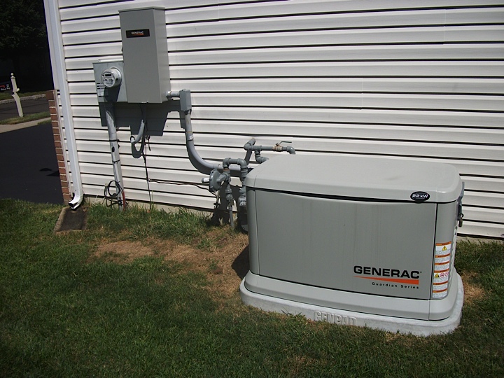
We purchase the generator that best fits your electricity needs. We file all township electrical and gas permits, deliver your Generac standby generator and transfer switch, prepare the mounting pad, run all gas piping and electrical conduit, and test the system under load.
 STEP 3 • AUTOMATIC PROTECTION
PEACE OF MIND
Have comfort knowing that your generator has you covered for every season and every storm. Whether you are asleep upstairs or away on vacation, your standby system automatically detects blackouts, powers your home within seconds, and shuts down when grid power returns.
Second-by-Second: How an Automatic Standby Generator Works During a Power Outage
Unlike a portable generator that sits in a shed waiting for you to haul it outside, pour gasoline, start a pull-cord engine, and run extension cords through a cracked window, a whole-house standby generator is permanently wired into your home's electrical system via an Automatic Transfer Switch (ATS) and permanently piped to your natural gas utility line or liquid propane tank.
Here is the exact technical sequence that occurs when a storm knocks out PECO utility power to your neighborhood:
| Elapsed Time | System Stage | What Happens Inside the Transfer Switch & Generator |
|---|---|---|
| 0.0 Seconds | Utility Voltage Dropout | The generator controller continuously monitors incoming utility voltage across Leg 1 and Leg 2 (nominal 240V AC). When utility voltage drops below the dropout threshold (typically 60%–65% of nominal, or ~156V AC), the controller initiates its outage timer. |
| 1 to 5 Seconds | Line-Interrupt Verification Delay | To avoid starting the engine during a brief 1-or-2-second utility recloser blink, the controller counts down a programmable 5-to-10-second verification delay. |
| 6 to 10 Seconds | Engine Cranking & Warm-Up | The controller opens the electronic fuel solenoid valve, sets the stepper-motor choke/mixer, and engages the 12V DC starter motor. Once the engine fires and reaches 3,600 RPM (60 Hz), the voltage regulator stabilizes output at 120/240V AC. |
| 10 to 15 Seconds | Automatic Transfer Switch Actuation | The transfer switch solenoid throws the heavy-duty mechanical contactor from the Utility position to the Generator position. This mechanically and electrically isolates your home from the street grid (preventing dangerous backfeeding) while connecting generator power to your house panel. |
| 15+ Seconds to Days/Weeks | Continuous Regulated Operation & Load Management | Your home's lights, refrigerator, furnace, sump pumps, well pump, and air conditioning operate normally. If equipped with Smart Management Modules (SMMs), heavy 240V appliances stagger their start times sequentially over 5-minute windows to prevent surge overload. |
| Grid Return + 15 Seconds | Utility Return Verification & Re-Transfer | When utility voltage returns and remains stable above the pickup threshold (~80% nominal voltage) for 15 continuous seconds, the transfer switch smoothly switches your home back to utility power. |
| Re-Transfer + 60 Seconds | Engine Cooldown & Standby Reset | The generator continues running with no electrical load for 60 seconds so the cooling fan can dissipate cylinder-head and alternator heat, then shuts off the fuel solenoid and returns to automatic standby monitoring mode. |
Our 8-Phase Turnkey Field Installation Protocol
Curious what happens on installation day at your home in Feasterville, Newtown, Doylestown, Bensalem, or Montgomery County? Here is how our crew executes a clean, code-compliant installation:
Phase 1: NEC Article 220 Load Calculation & Surge Profiling
We perform a formal NEC Article 220.82/220.83 optional standby load calculation. Beyond adding up running wattages (lights, refrigeration, blowers, electronics), we inspect the Locked Rotor Amps (LRA) on your central air conditioning compressor data plate and well pump motor to ensure the generator's surge capacity (kVA) can start the largest motor without excessive voltage dip.
Phase 2: Site Layout, Zoning Setbacks & NFPA 37 Clearance Verification
We select an exterior location that minimizes run lengths to both your gas meter and electric panel while satisfying NFPA 37 rules (minimum 5 feet from operable windows, doors, and vents; 18 inches from the house wall; 3 feet of service clearance on sides and front) and local township property-line setbacks.
Phase 3: Municipal Electrical, Gas & Building Permits
Home Generator Installations, LLC prepares and submits the permit application package to your local township building department—including site plot plans showing setbacks, manufacturer specification sheets, UL 2200 listings, gas pipe sizing diagrams, and electrical one-line risers.
Phase 4: Composite GenPad or Framed Concrete Pad Installation
A standby generator weighs between 385 lbs and 550+ lbs and vibrates slightly during operation. We excavate and compact a crushed-stone base and install either a pre-cast steel-reinforced composite GenPad or a custom timber-framed poured concrete slab leveled with a digital spirit level so crankcases and oil level sensors sit dead-level.
Phase 5: Natural Gas or Liquid Propane Piping & Pressure Testing
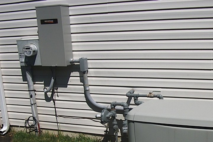
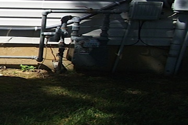
We install Schedule 40 black iron piping (primed and painted for corrosion resistance) or underground yellow polyethylene (PE) gas pipe with anodized transition risers and tracer wire. Every gas run includes an accessible manual shutoff valve, a code-required sediment trap to catch pipe scale or moisture before it reaches the generator's demand regulator, and a flexible stainless-steel fuel connector to isolate engine vibration. We pressure-test the line with a gauge to verify zero leaks.
Phase 6: Automatic Transfer Switch (ATS) & Conduit Wiring
For whole-house systems, we coordinate utility disconnect and mount a 200A service-entrance rated Automatic Transfer Switch between your electric meter and main breaker panel. We run power conductors (`THHN/THWN-2` copper or `XHHW-2` aluminum sized per NEC Table 310.16) alongside 240V utility sensing wires and DC control leads inside weatherproof Schedule 80 PVC or liquidtight conduit to the generator.
Phase 7: Commissioning, Manometer Testing & Simulated Outage Test
Before turning the system over to you, we fill and check synthetic engine oil, install a load-tested 12V AGM/lead-acid Group 26R battery, connect a digital manometer to the test port on the internal demand regulator, and pull the main utility breaker to simulate a real blackout. We verify:
- No-load and full-load AC voltage (`240V AC +/- 2%`) and frequency (`60.0 Hz`).
- Dynamic fuel pressure stability (`5.0 to 7.0 inches W.C.` for Natural Gas; `10.0 to 12.0 inches W.C.` for Liquid Propane) while both the generator and household gas appliances are firing at maximum capacity.
- Clean transfer and re-transfer timing, load-shedding module operation, and weekly Quiet-Test exercise programming.
Phase 8: Final Township Inspection & Homeowner Walkthrough
We meet the municipal electrical and building inspectors for final sign-off, register your Generac warranty, and walk you through the status indicator lights (Green = Ready, Yellow = Maintenance Interval, Red = Fault Alert), manual shutoff switches, and mobile monitoring options.